Backpack Build
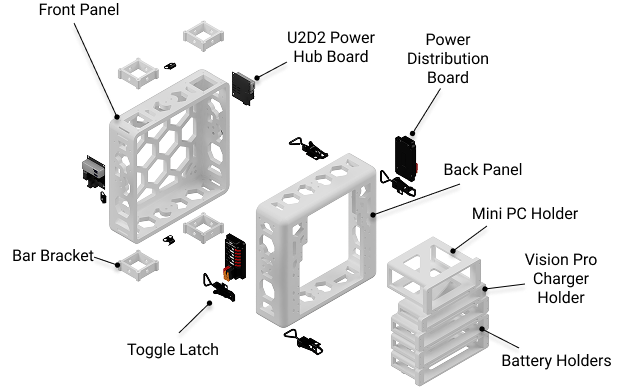
In this section, we will walk through all of the necessary steps fabricate and assemble the ModPack core.
Before You Begin
The U2D2 must be assembled onto the U2D2 Power Hub Board before installing it in the backpack.
Tools Required
Tools Required
- Soldering iron with heat-set insert tip
- Hex wrench set (2.5 mm, 3 mm, 5 mm)
- Small crescent wrench
3D Prints
Tool Required
FDM 3D printer (Bambu Labs H2D or X1 Carbon recommended)
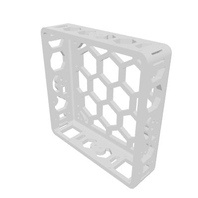
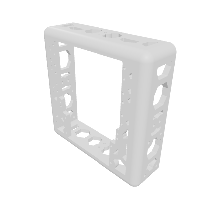
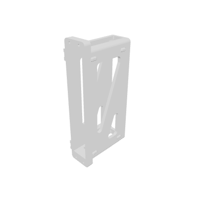
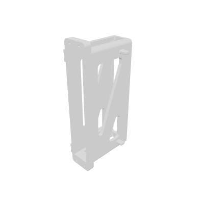
All backpack components were printed on a Bambu Labs H2D (large panels) or Bambu X1 Carbon (smaller pieces). The backpack is split into two halves so each half fits on a standard print bed.
| Parameter | Value |
|---|---|
| Material | PLA |
| Infill | 15% |
| Infill Pattern | Gyroid |
| Layer Height | 0.2 mm |
| Wall Count | 2 |
| Nozzle Diameter | 0.4 mm |
| Support Strategy | Tree |
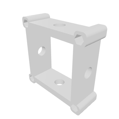
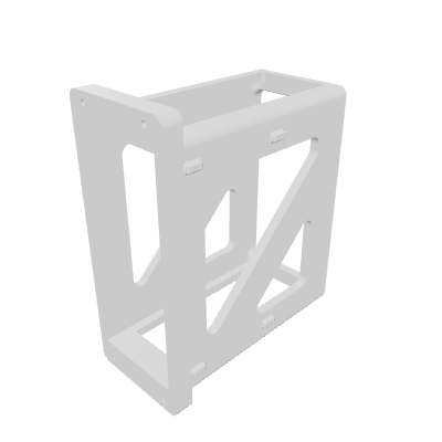
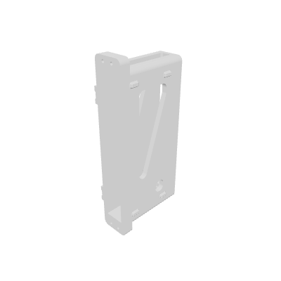
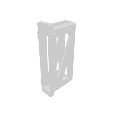
Heat Set Inserts
After printing, we install heat set inserts to provide rigid mounting points for bolts. We find a good temperature for the soldering iron is 220 C.
Tool Required
Soldering iron, optionally with a heat-set insert tip.
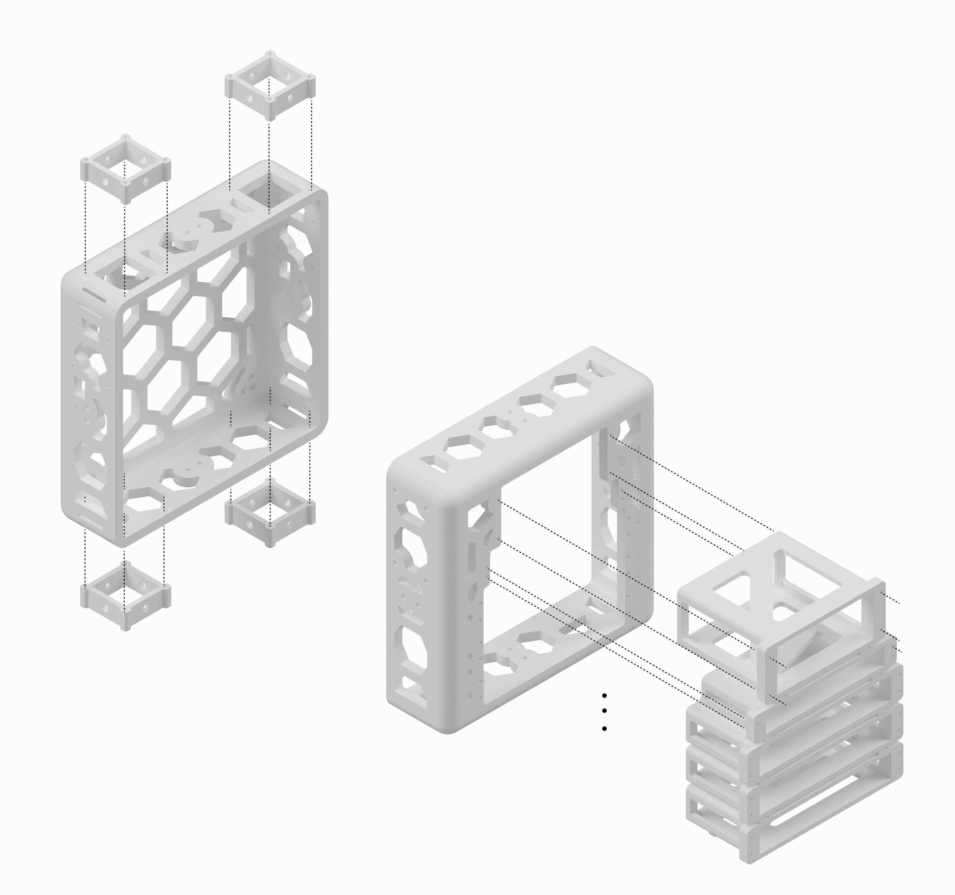
Use the above diagram to find the heat set insert locations. Use the 94180A321 M2.5x3.4 heat-set inserts.
Brackets
Once heat sets are in, use the 97763A822 M5x16 button head screws to fasten the 3D printed brackets.
Latches
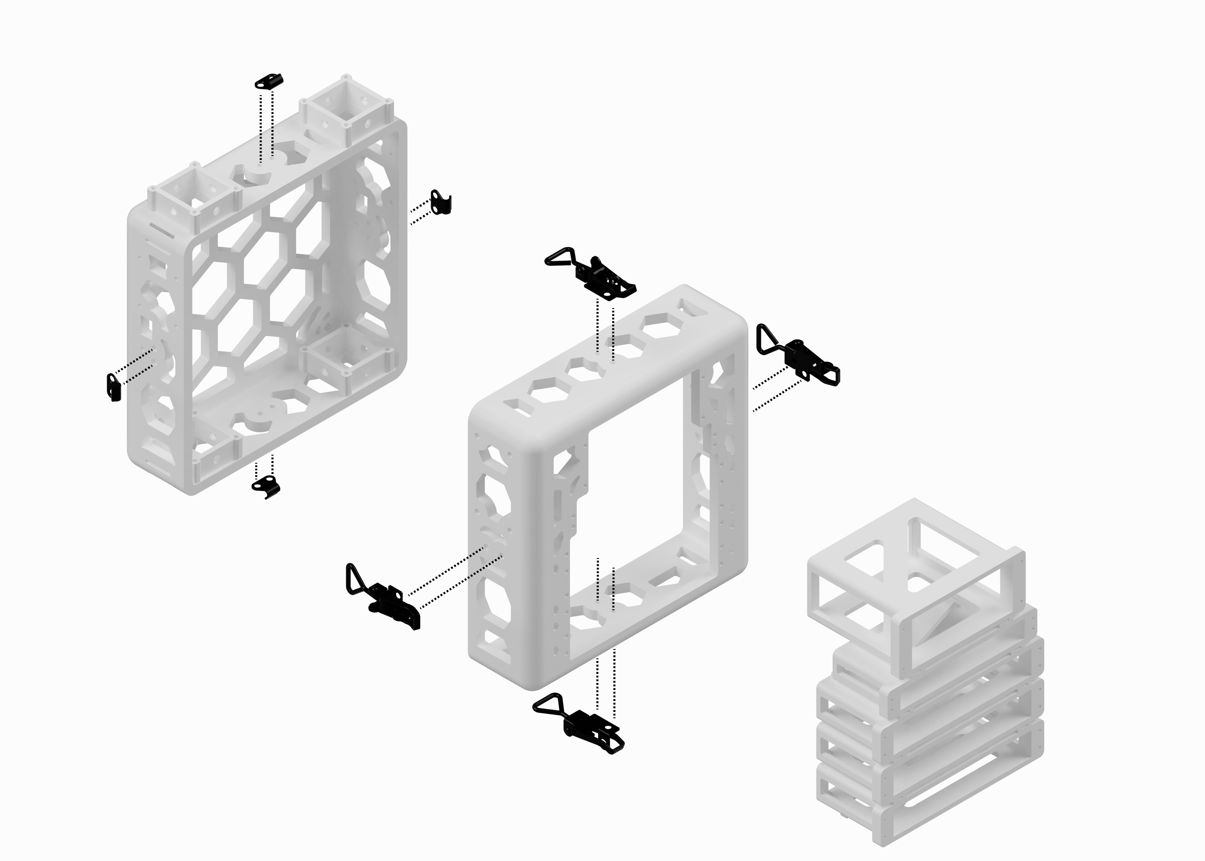
Next, install the latches using 97763A822 M5x16 button head screws and 93625A200 M5 nylon lock nuts.
Mounting Arm Bars
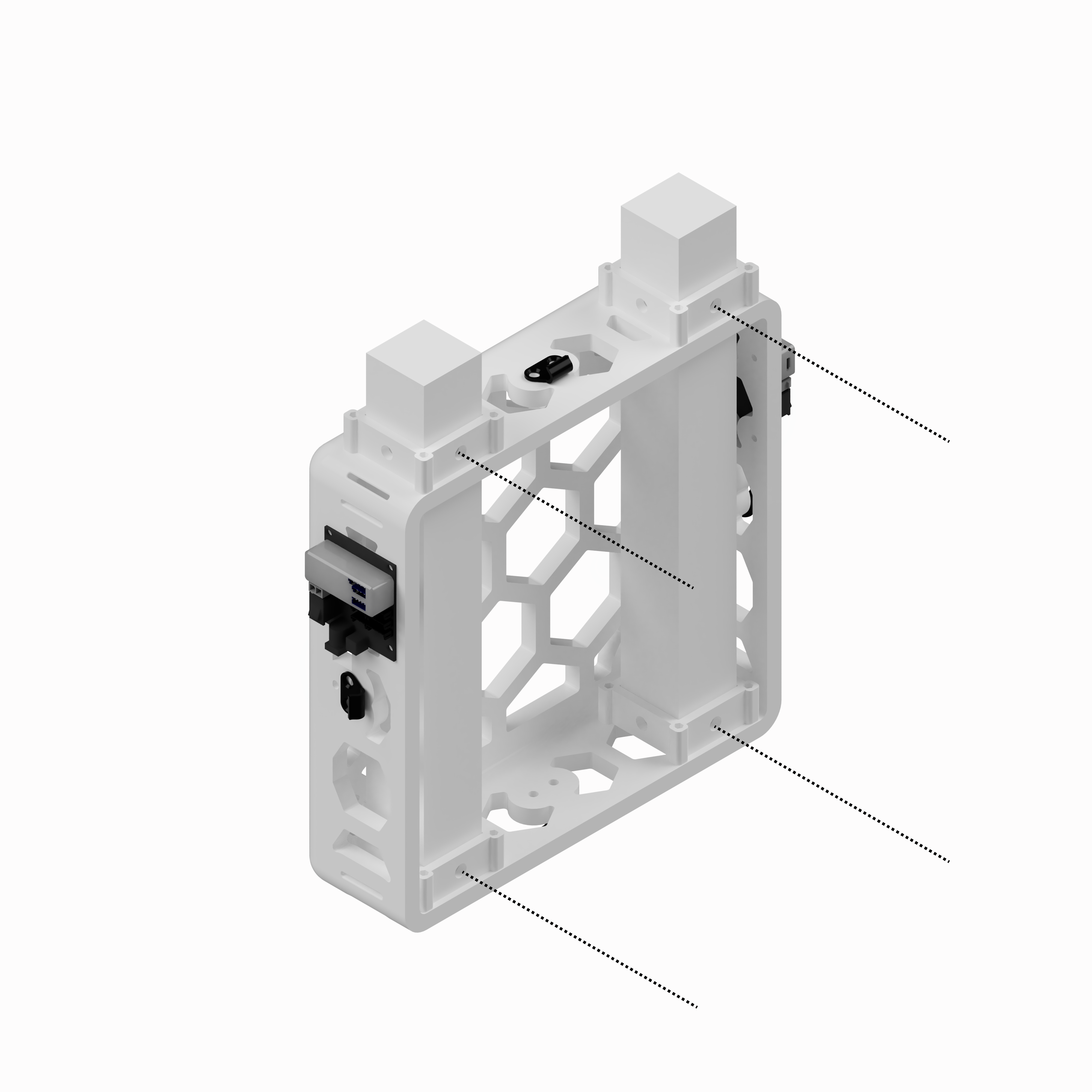
Mounting the arm bars
The leader arms mount to two vertical 40×40 T-slot extrusion bars that slot into the top of the front panel of the backpack. Once you have installed the bar brackets (x4) with the 91292A832 M2x8 socket head screws, slide the 40x40 bars into place, securing them with following the dotted callouts with 97763A822 M5x16 button head screws and the T-slot sliding T-nuts.
Mounting Electronics
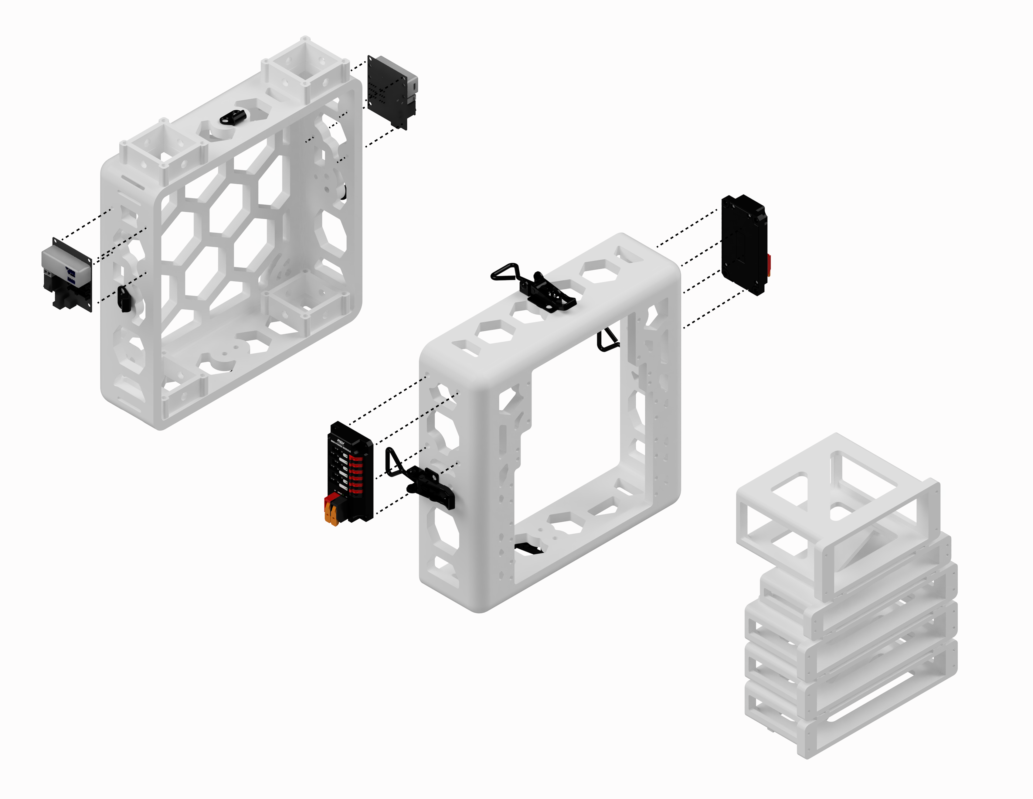
U2D2 Power Hub and REV Mini PDP
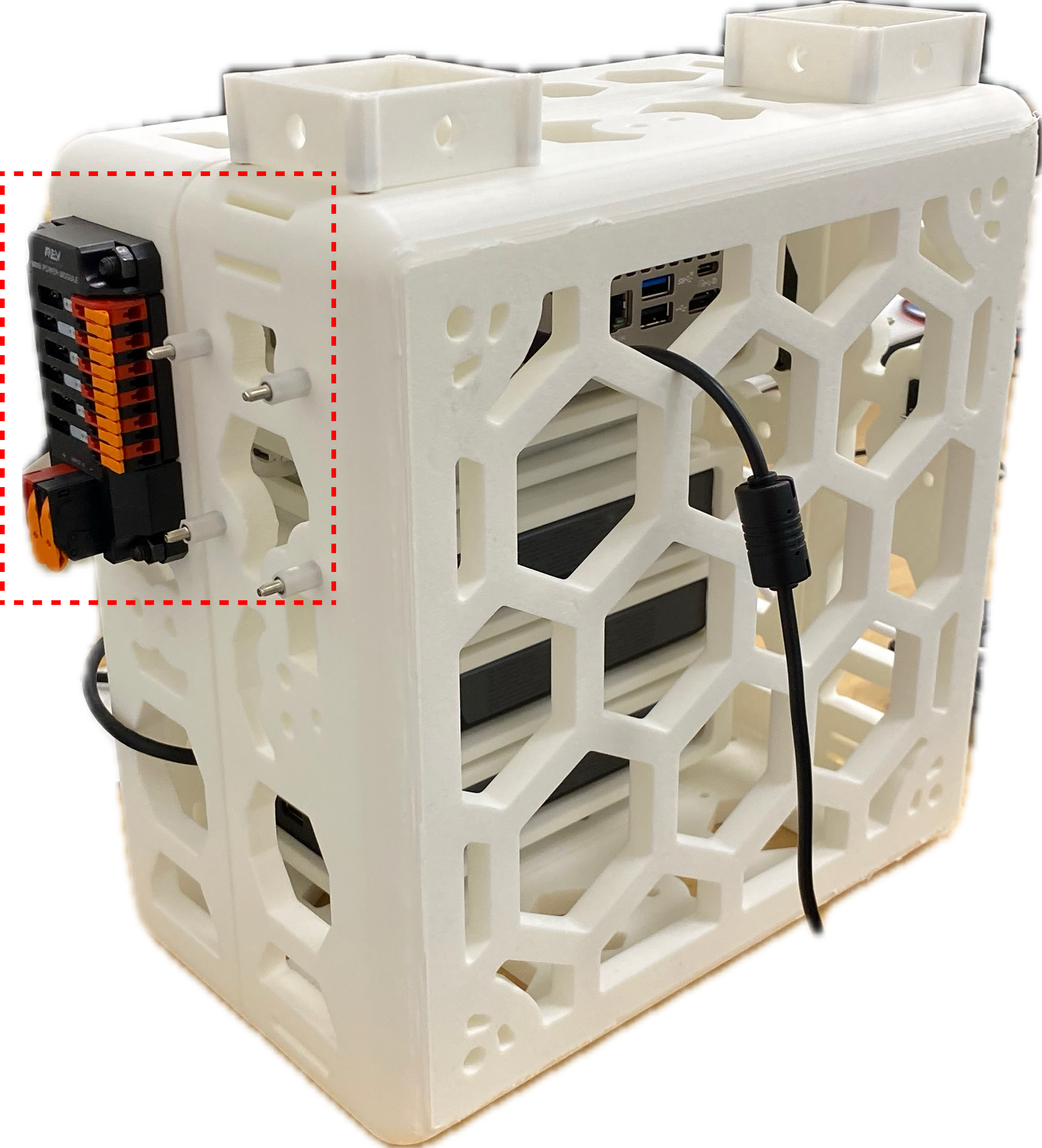
Use the provided screw offsets, securing the back of the U2D2 board with the 91292A016 M2.5x12 socket head screws and 93475A210 M2.5 washers.
With the bolt head (91290A252 M5x25 socket head screw) on the inside of the backpack, mount the REV Mini Power Module to the side of the backpack, securing with a 93625A200 M5 nylon lock nut.
Shelves
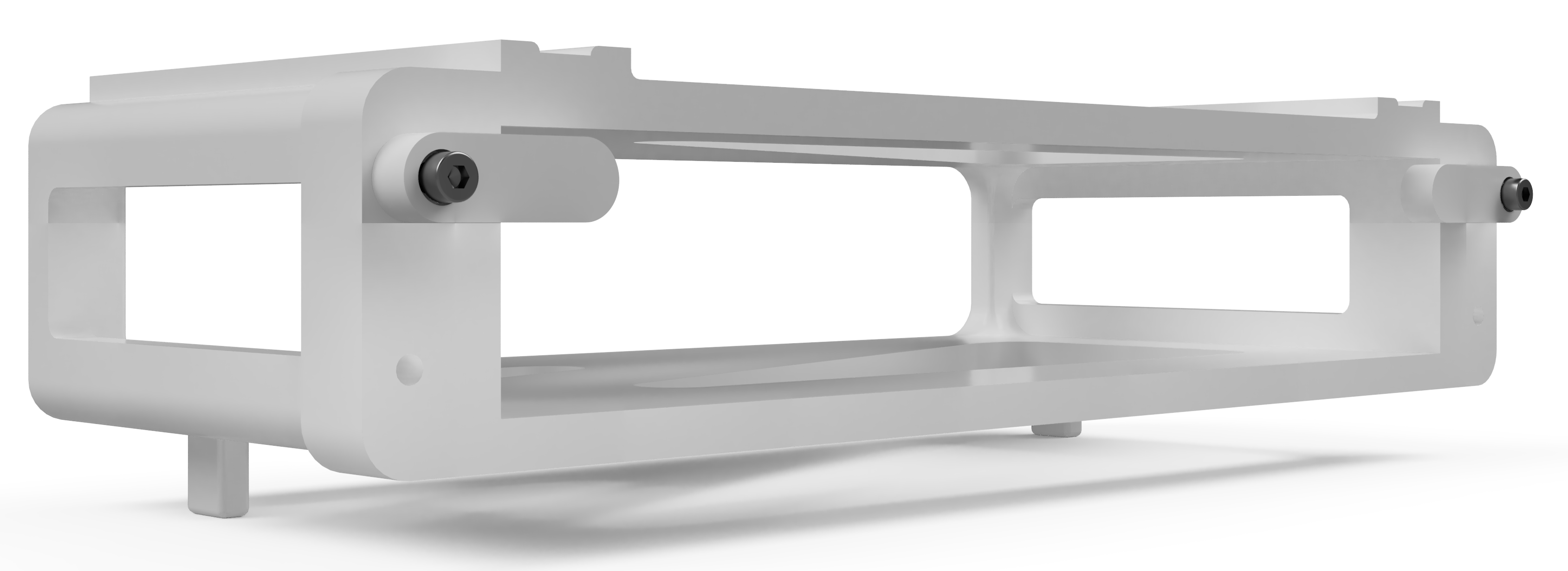
Install the shelves in bottom-up order, as the bottom shelf has a set of stands that cannot be fit in the backpack if the shelf above is installed. Pictured below is the bottom-most shelf along with the attached switches that hold the components in. Tighten such that you can still move the latches to slide components in and out.
iPhone Mount
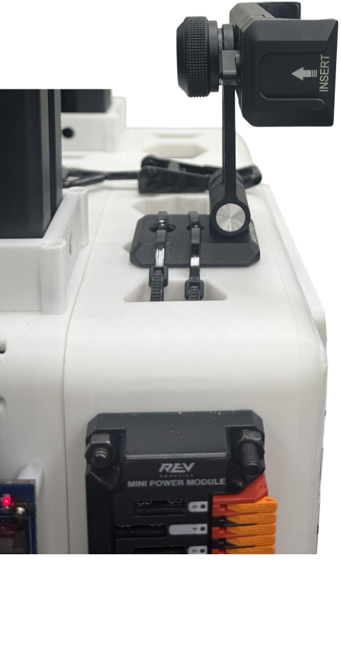
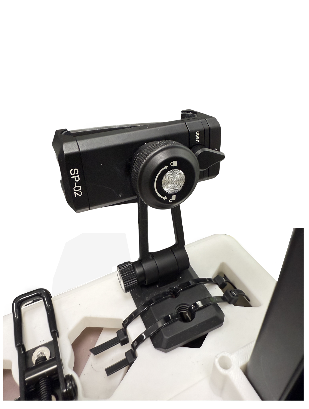
Attach the iPhone mount with zipties by looping the ties through the backpack, as shown below.
Backpack Straps
Upper straps: Loop a strap through the backpack, then assemble using the multi-purpose buckle set so that the buckle faces outwards.
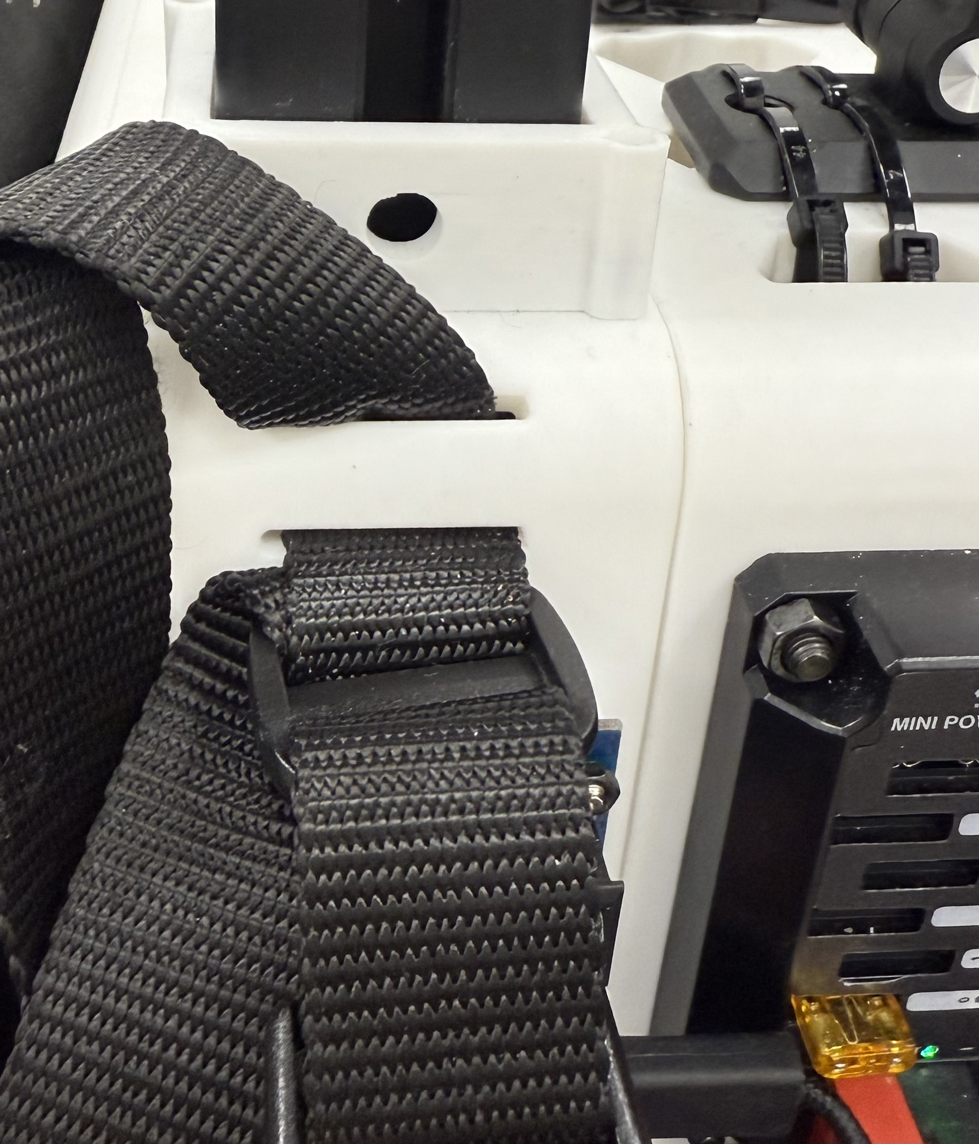
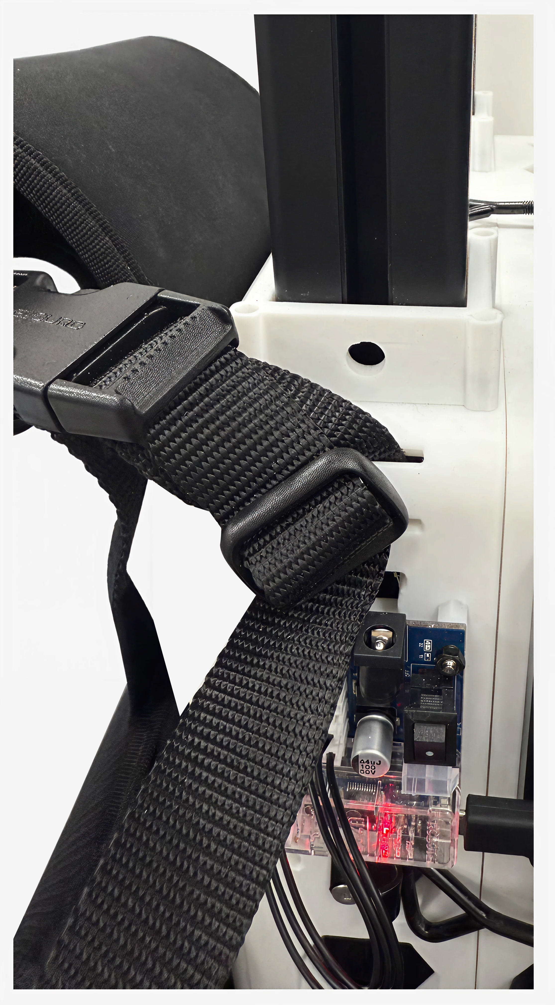
For buckle assembly, see specific manufacturer instructions here.
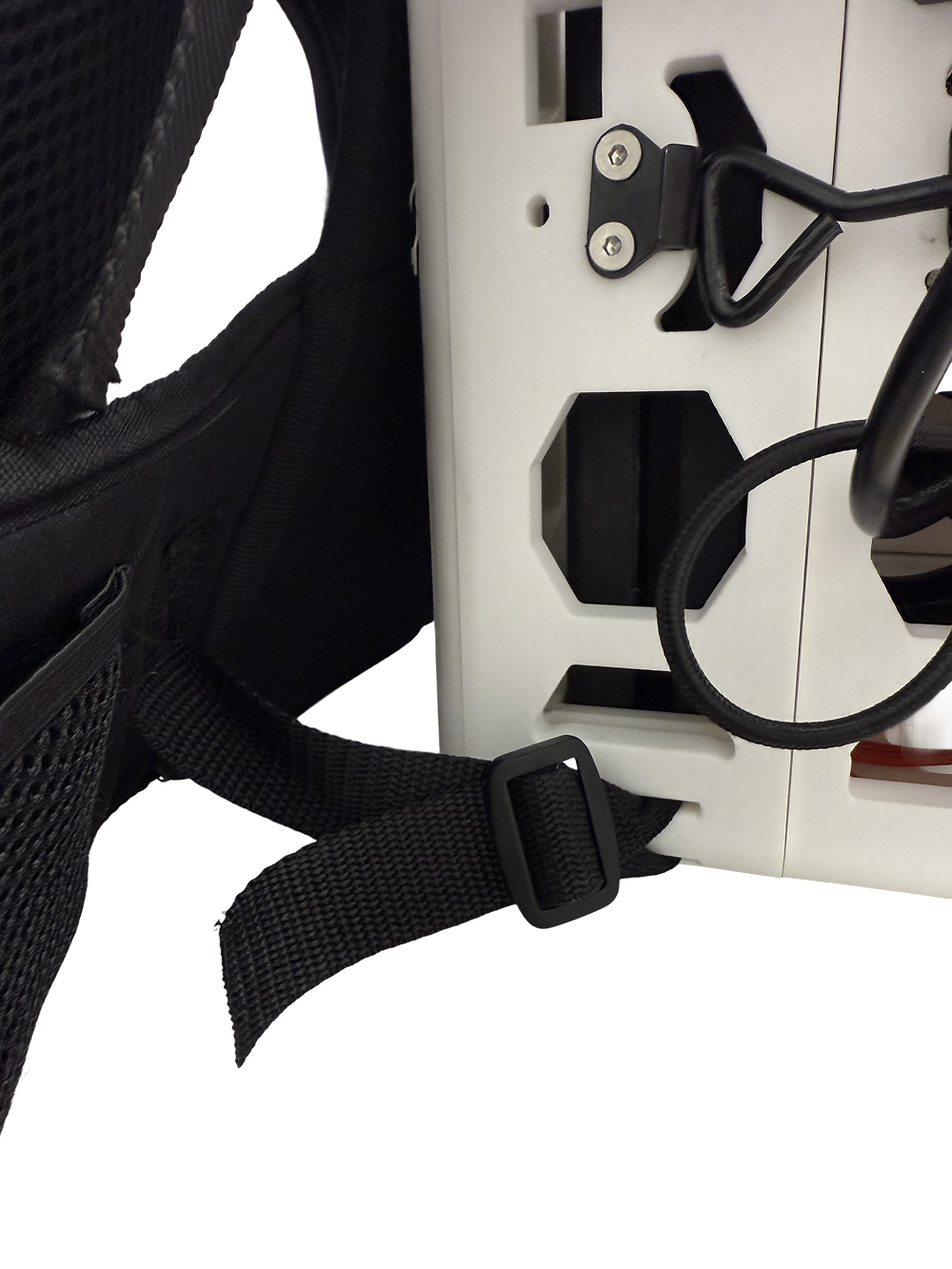
Lower straps: Loop the harness strap directly through the backpack hole as shown below. More detailed installation steps can be found on the manufacturer's page. Adjust tightness as needed.